


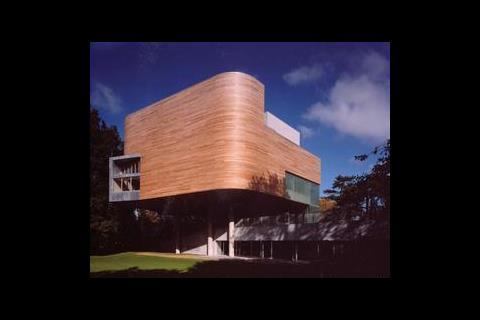
If you were told that this gallery cost just ┬Ż6m to build, rises up from a footprint the size of two tennis courts and expects to consume 75% less energy than a typical scheme, you might not believe it. But, says Stephen Kennett, itŌĆÖs all true
The judges were unanimous when they chose the Lewis Glucksman Gallery in Cork as the winner of this yearŌĆÖs ąŪ┐š┤½├Į Services Award for projects under ┬Ż20m. In their summation they commented that it was ŌĆ£an outstanding, unusual project executed in a creative fashionŌĆØ ŌĆō and this despite the fact that it was delivered on a very tight budget.
The cost of procuring the building was set at ┬ż12m (┬Ż8.3m), with ┬ż8.5-9m (┬Ż5.9-6.2m) earmarked for construction. ŌĆ£It was a constraint that was never relaxed despite the architectural vision for the project,ŌĆØ says John Burgess, associate with Arup and engineer in charge of the projectŌĆÖs M&E design.
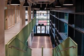
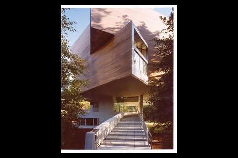
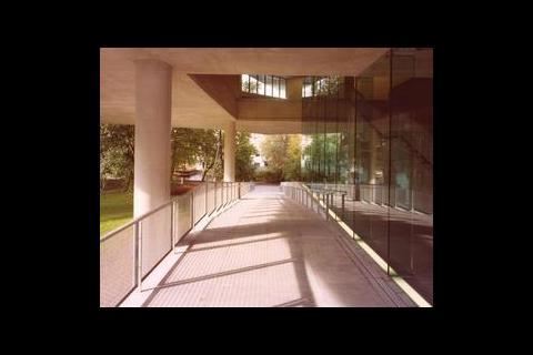
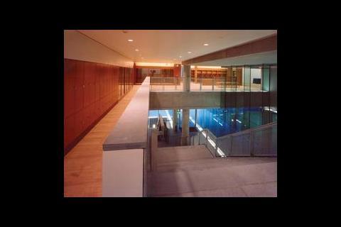
OŌĆÖDonnell & Tuomey is the architect behind the scheme and had the job of squeezing the 2350 m2 building onto a site that is bordered by the river Lee and a large number of mature trees. In response to this the architect kept the footprint of the building to the area of the two tennis courts it replaces and built tall. The buildingŌĆÖs sev en floors house four exhibition spaces, multifunction rooms, lecture facilities, a cafe and a basement gallery store.
The exhibition spaces were central to the brief and provide public galleries for University College CorkŌĆÖs modern art collection, as well as travelling and special exhibitions.
Throughout the design and construction the architect stuck religiously to its vision, Burgess says, and delivering that vision required some real ingenuity from the services engineers.
The original client brief asked for a windowless internal gallery held under close control conditions, with naturally ventilated wrap-around perimeter galleries. However, Burgess says the building form was so unusual it would have cost more to naturally ventilate the spaces than to provide mechanical cooling. ŌĆ£We said we could use displacement ventilation, and although weŌĆÖre not naturally ventilating it per se it does mean we have a means of controlling conditions inside.ŌĆØ When relative humidity control is not required, the ventilation system maximises the opportunity for free cooling as the minimum air supply temperature is 19┬░C.
To reduce the buildingŌĆÖs environmental footprint the displacement system that has been adopted throughout the building is coupled with a ground energy thermal transfer system (GETTS). This has been developed to minimise the energy needed for heating, cooling and humidity control and exploits the water in the alluvial gravel deposits beneath the site (see box, over the page).
The building uses cast in situ concrete for the basement to second floor, above which it reverts to a steel frame with composite walls. Providing plantrooms, routes and risers has meant going into normally out of bounds zones. The only straight vertical line through the building is the lift shaft and squeezed into the single central riser alongside this is the electrical riser, low temper- E E ature hot water, chilled water, gas supply and kitchen extract. ŌĆ£The architect wanted to maximise the public space and maintain a clean, uncluttered look,ŌĆØ says Burgess. ŌĆ£The knock on effect was that routing the services was very difficult and time consuming.ŌĆØ
On top of this, all systems have been designed to minimise noise intrusion to the gallery spaces and this has resulted in larger, low velocity duct distribution systems and acoustic attenuation on all plant, including the use of specially lined drainage systems. ŌĆ£We sat down early on in the design with the structural engineers to coordinate how we would route the ductwork through the building structure, as well as co-ordinating with the concrete contractor, as most of the electrical services are routed in conduit embedded into the concrete floor slabs.ŌĆØ
The four interlocking exhibition spaces vary in size and are staggered over the buildingŌĆÖs three upper floors. Air is supplied discreetly at low level, mainly from bespoke window floor boxes, but also through wooden floor grilles, slots built into the stair risers and storage cupboard pedestals. Most of the ductwork is brought down inside the composite walls, occupying the 200 mm air gap, and is then brought along in the spaces between the floor and wall joists to serve the gallery spaces. Return air is taken out through shadow gaps between the ceiling and walls.
Given the volume of the gallery spaces, ventilation rates werenŌĆÖt a driving factor; the air-handling units provide three air changes an hour rather than six. Even so, specially built units had to be used to fit the available space. The AHUs that serve the E E wrap-around galleries are all housed in the fifth floor plantroom, while the AHU serving the central close control gallery is split in two, with supply and return sections housed in separate plant spaces. A third AHU supplies the basement gallery store. This is a large unit given its 100 litre/s supply mainly due to the carbon filters, panel bag filters, heating, cooling and dehumidification plant it contains.
The heating, ventilation and air-conditioning systems are controlled through an energy management system using triple redundancy temperature and humidity control for each of the gallery spaces, playing an important role in providing user flexibility.
Early predictions by Arup showed that by using the GETTS system, energy consumption for the assumed hours of occupation would be around 400,000 kWhr, or 175 kWhr/m2/annum. This is about 25% of the levels expected from a conventional chiller and boiler heating system, amounting to a reduction in CO2 emissions of 256 tonnes a year (from 351 to 95).
Since the building was opened in October last year energy consumption has been monitored, but so far it is higher than predicted. ŌĆ£WeŌĆÖve been monitoring energy use and weŌĆÖre not meeting those targets, mainly because the university is operating the wrap-around galleries in dehumidification mode,ŌĆØ says Burgess. ŌĆ£The initial brief was only for close control in the one internal gallery but because the gallery now has the option of a better quality environment in the wrap-around galleries itŌĆÖs using it and consuming more energy than it should. We need to get the curators to relax the conditions when there isnŌĆÖt an exhibition on.ŌĆØ
Burgess is also hoping to reduce energy consumption further by switching off the condensing gas boilers. These provide back-up should the GETTS system fail and also supply high temperature hot water for the trench heaters at the base of the showcase windows and the radiant panels used to offset the risk of condensation. ŌĆ£WeŌĆÖre going to try it next year and see what happens, if we do have a problem with condensation we can simply turn them back on, but we could virtually eliminate all of our gas consumption.ŌĆØ
Apart from this, the building is living up to expectations. For the university, the gallery represents a breakthrough in the standard of new buildings it can expect, capturing the imagination of the public while also achieving the triple bottom line of sustainable design. And the demanding architectural and aesthetic objectives have been met, despite the highly serviced nature of the building. For Fiona Carney, director of the gallery, it is a huge success. ŌĆ£It been delivered within the budget of ┬ż12m, but another zero could be added to that number and it would not look out of place.ŌĆØ
Lighting
The design team had to carefully balance the need for daylighting in the wrap-around galleries with the need to limit solar gains and direct glare, and the architectŌĆÖs wish to retain the views south and west along the river. The two-storey cantilevered pop-out windows help achieve this and are fitted with motorised blinds to control daylight penetration.
Arup worked closely with the architect to create the artificial lighting scheme. The design intent was for very simple, clean lines and clutter-free ceilings, with the majority of the fittings recessed. OŌĆÖDonnell Toumey wasnŌĆÖt overly enthused with the fittings available in the market place and this led to a large number of modified and bespoke fittings being used.
Without full photometric data available it was up to the design team to establish how the fittings would perform. Burgess explains: ŌĆ£We did our calculations based on a similar type of fitting to predict the lighting levels, giving us an indication of what to expect, and then built a prototype. These were brought to site and tested through a number of iterations to establish lux levels, spacing and other parameters.ŌĆØ
The lighting levels in the gallery spaces are fairly typical of those set out in the CIBSE guides. In the wrap-around galleries recessed ceiling-mounted, dimmable fluorescent wall washers with UV filters provide ambient lighting. These are arranged in a continuous linear array to provide a uniform wash. A recessed lighting track is provided for spotlights to pick out free standing exhibits within the space.
In contrast, the internal gallery is free of daylight and uses track-mounted tungsten halogen spots to create a more focused lighting effect. These are again fitted with UV filter and sculpture lenses which can be adjusted to provide flexibility to suit the exhibits on show. In other areas, uplighting on the concrete soffit creates a sparkling effect, created by sandblasting the concrete to reveal the reflective mica.
An Erco analogue lighting control system provides up to 18 pre-set scenes throughout the gallery spaces to suit a variety of occasions. Local controllers are installed in each of the galleries to allow curators to change settings
as required. The lighting system is also linked to the multizone intruder alarm system, automatically switching on all the lights when an alarm is raised.
The intruder alarm system provides separation of the gallery and restaurant spaces and is also supported by a digital CCTV system, which can be set up to protect artwork by monitoring the position of the pixels in a painting and raising an alarm if these change.
Ground energy thermal transfer system

The main source of heating and cooling for the gallery is provided by the ground energy thermal transfer system. Arup teamed up with local ground source heat pump installer Dunstar to develop the system, which uses two water cooled chillers to provide a total cooling capacity of 170 kW. In addition, 200 kW of heating is simultaneously provided by harnessing the heat rejected from the condensers. This is fed directly into the heating circuits to supply the heating coils in the air-handling units, radiators and underfloor heating in the foyer and toilets.
Two buffer tanks are set up to receive any excess heat or coolth generated by the system. To regulate the water temperature in these vessels and prevent it from freezing or boiling they are connected via a heat exchanger to the ground well water, which is at a constant 12-13┬░C. ŌĆ£In the summer they take away the excess heat from the building and discharge it into the river,ŌĆØ says Burgess. ŌĆ£In the spring and autumn when youŌĆÖre heating as much as youŌĆÖre cooling because of dehumidification you end up just running the chillers and you donŌĆÖt actually run the pumps at all.ŌĆØ
The ground water is then discharged to a holding tank for use in toilet flushing and landscape irrigation with any excess flowing into the river Lee.
One of the most frequent modes of operation for the system is dehumidification. With a relative humidity set point of 50% in the galleries at 21┬░C and ambient relative humidity levels of 60-90%, the air-handling units must operate both cooling coils ŌĆō to strip out moisture by lowering the incoming air to 12-13┬░C ŌĆō and reheat coils to raise air temperatures back up to the room supply set point.
ŌĆ£As the GETTS provides both chilled water and heating water simultaneously from the water cooled chillers, a coefficient of performance of eight can be achieved,ŌĆØ says Burgess. Gas fired condensing boilers are installed in the top floor plant room to supply back-up to the GETTS system.
While the cost of the GETTS installation is higher than a conventional boiler and water-cooled chiller set up, University College Cork was able to secure a grant from Sustainable Energy Ireland (the Irish funding body for EU grants for sustainable energy) for 50% of the capital difference. Holistically the scheme is also boosted by the on campus combined heat and power plant which supplies all the electricity to the building.
The Lewis Glucksman Gallery, University College Cork
Client University College Cork
Architect OŌĆÖDonnell Tuomey Architects
M&E consulting engineer Arup
Structural engineer Horgan Lynch Partnership
Civil engineer Horgan Lynch Partnership
Quantity surveyor Andrews OŌĆÖKeefe Collins
Main contractor PJ Hegarty
Mechanical contractor Mercury Engineering
Electrical contractor IIF PMEC
Mechanical suppliers
AHUS Danann Clean Air Services
Air curtains ATC
Boilers/burners/flues Euro Gas
Ceiling diffusers Aervent Group
Chillers ŌĆō ground source heat pump Dunstar Geothermal Energy
Control valves Sauter
Dampers Aervent Group
Duct reheat coils Aervent Group
Ductwork OŌĆÖ Sullivan Darcy
Extract fans Control Aer, Aervent Group
Fan coil units Aervent Group
Floor grilles Aervent Group
Heat exchangers Eurofluid
Gas fired hot water cylinder Humidifiers JS Electrovac
Perimeter heating HJ Aircon ŌĆō Trench heaters
Pumps Wilo and Grundfoss
Pressurisation units Hevac
Radiant panels HJ Aircon
Radiators Merriott
Sound attenuation Dannan
Tanks Killarney Plastics
Underfloor heating Valve Control Systems (Wirsbo)
Valves BSS (Crane)
BMS Standard Control Systems (Trend)
Water leakage detection Sontay
Electrical suppliers
CCTV Electronic technology
Electrical accessories Erco Lighting Ireland
Fire alarm/detection Firecrest Safety Systems
Lighting controls Erco Lighting
Luminaires EWL, Kellihers Electrical, Erco Lighting
LV switchgear ASC
Engineering data
Gross floor area (gfa) 2355m2, plant rooms 300 m2, kitchens 105 m2, toilets 65 m2, dining 150 m2
Contract details
Tender date: 17/6/02
Tender system: traditional issued to eight contractors
Form of contract: GDLA, contract period: 2 years
External design conditions
Winter -1┬░C /100% sat
Summer (a/c) 24┬░C db, 24┬░C wb
Internal design conditions
Winter 19┬░C min, 50% relative humidity +/-5% (for gallery)
Summer (non a/c)&▓į▓·▓§▒Ķ;25┬░░õ
Summer (a/c) 21┬░C, 50% relative humidity +/-5% (for gallery)
Circulation and toilets 21┬░C max
U-values (W/m2K)
Walls 0.20, floor 0.08, roof 0.26, glazing 2.0 (including frame)
Noise levels
Offices NR 40, toilet and circulation NR40,
Exhibit areas NR 30
Target energy use for HVAC systems (gfa) Gas 75 kWh/m2/y, Electricity 114 kWh/m2/y
CO2 target 40 kg/m2/y (power from local CHP)
Loads
Calculated heating load 375 kW
Installed heating load natural gas boilers 2 ├Ś 102 kW, gshp 1 ├Ś 90 + 1 ├Ś 144 kW (234 kW total)
Calculated cooling load 200 kW
Installed cooling load 1 ├Ś 75 + 1 ├Ś 120 kW (195 kW total)
Ventilation power average at 0.45 W/litre/s
Scheduled supply air temperature 19┬░C summer, 26┬░C winter
Room temp 21┬░C min, 21┬░C max
Fresh air 30% min (12 litres/s/per person)
Max recirculation 100% EMWU
Filtration EU4 & EU8 plus carbon filtration for inner gallery
Primary air volumes
Total fan power 11 W/m2
Main wrap around galleries AHU 4 m3/s
Inner gallery AHU 0.86 m3/s; galley store AHU 0.1 m3/s
Private dining ventilation 0.357 m3/s; kitchens 2.91m3/s
Water distribution circuits
LTHW 82┬░C flow, 71┬░C return; LGHW 50┬░C flow, 40┬░C return; DHWS 60┬░C flow, 50┬░C return; chilled 6 ┬░C flow, 12 ┬░C return
Lux levels (average)
Office 500 lux, kitchen 500 lux, toilets 150 lux
Stairs 150 lux, gallery areas: dimmable to suit exhibition/display
Glare index: 19-22
Costs
Total construction cost (excl VAT fees)&▓į▓·▓§▒Ķ;┬Ż6.3│Š
ąŪ┐š┤½├Į services total (excl VAT)&▓į▓·▓§▒Ķ;┬Ż1.244│Š
Mechanical cost ┬Ż581,000
Elecetrical cost ┬Ż563,000
Lifts cost ┬Ż100,000
Total net cost&▓į▓·▓§▒Ķ;┬Ż2675/│Š2
ME & lifts cost ┬Ż528/│Š2
Mech services cost breakdown (based on gfa)
Plantroom pipework, boiler flues etc&▓į▓·▓§▒Ķ;┬Ż17/│Š2
LPHW system&▓į▓·▓§▒Ķ;┬Ż19/│Š2
LGHW system (55┬░C)&▓į▓·▓§▒Ķ;┬Ż14/│Š2
Chilled water system&▓į▓·▓§▒Ķ;┬Ż15/│Š2
Water services&▓į▓·▓§▒Ķ;┬Ż17/│Š2
Ventilation&▓į▓·▓§▒Ķ;┬Ż32/│Š2
Air conditioning system&▓į▓·▓§▒Ķ;┬Ż7/│Š2
Ground source heat pump&▓į▓·▓§▒Ķ;┬Ż59/│Š2
Above ground soils and wastes&▓į▓·▓§▒Ķ;┬Ż5/│Š2
Power and controls (MCC & BMS)&▓į▓·▓§▒Ķ;┬Ż28/│Š2
Fire services (FM200 extinguisher to store)&▓į▓·▓§▒Ķ;┬Ż7/│Š2
Gas services&▓į▓·▓§▒Ķ;┬Ż5/│Š2
Commissioning&▓į▓·▓§▒Ķ;┬Ż10/│Š2
Drafting, documentation and training&▓į▓·▓§▒Ķ;┬Ż9/│Š2
Electrical services cost breakdown (based on gfa)
LV switchgear and submain cables&▓į▓·▓§▒Ķ;┬Ż20/│Š2
Lighting installation&▓į▓·▓§▒Ķ;┬Ż80/│Š2
Small power installation&▓į▓·▓§▒Ķ;┬Ż16/│Š2
ICT system&▓į▓·▓§▒Ķ;┬Ż6/│Š2
Intruder alarm system&▓į▓·▓§▒Ķ;┬Ż7/│Š2
CCTV system&▓į▓·▓§▒Ķ;┬Ż12/│Š2
Fire alarm system&▓į▓·▓§▒Ķ;┬Ż11/│Š2
VESDA system&▓į▓·▓§▒Ķ;┬Ż2/│Š2
Voice evacuation system&▓į▓·▓§▒Ķ;┬Ż5/│Š2
Lightning protection system&▓į▓·▓§▒Ķ;┬Ż1/│Š2
Cable tray conduit installation&▓į▓·▓§▒Ķ;┬Ż18/│Š2
Mechanical supplies&▓į▓·▓§▒Ķ;┬Ż16/│Š2
Refuge area telephone system&▓į▓·▓§▒Ķ;┬Ż2/│Š2
Earthing and bonding installation&▓į▓·▓§▒Ķ;┬Ż2/│Š2
Lifts including dumbwaiter&▓į▓·▓§▒Ķ;┬Ż40/│Š2
Structural details
Basement, Ground, 1st and 2nd Floor ŌĆō Cast in-situ Concrete
2nd, 3rd, 4th & 5th floor- Steel Frame
Second floor cantilevered deck 12m with 1.2m upstand beams
Lifts Goods and Person: 0.4m/sec
Refrigerant in Chillers: R407C
Downloads
Source
ąŪ┐š┤½├Į Sustainable Design
No comments yet